If you have checked the list of available blocks and need a feature that is not there, you can extend an existing block or create a new one. If the feature fits the behaviour of an existing block and can be added without breaking backwards compatibility, it is preferable to add it there. If there is a new type of behaviour it may be better to make a new block.
This page lists all of the framework features involved in making a block: finding a module for it, defining the interface, writing the simulation, writing the timing tests, documenting the behaviour, and finally writing the logic.
Architecture
An overview of the build process is shown in this diagram; the stages and terminology are defined below.
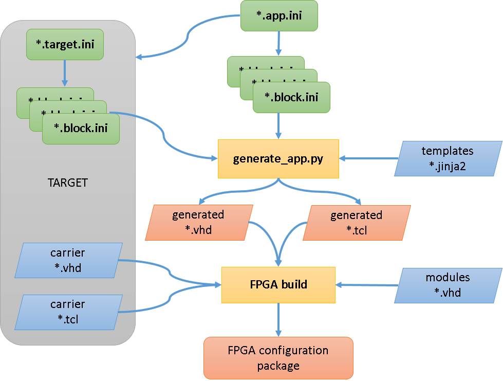
Modules
Modules are subdirectories in modules/ that contain block definitions.
If you are writing a soft block you will typically create a new module for it. If
you are writing a block with hardware connections it will live in a module for
that hardware (e.g. for the FMC card, or for that target platform).
To create a new module, simply create a new directory in modules/.
Block ini
The first thing to define when creating a new block is the interface to the rest
of the framework. This is an ini file containing all the information the
framework needs to integrate some VHDL logic into the system. It lives in the
module directory with the extension .block.ini. It consists of a top-level
section with information about the block, then a section for every
field in the block.
The [.] section
The first entry to the ini file describes the block as a whole:
[.]
description: Short description of the Block
entity: vhdl_entity
type: dma or sfp or fmc
constraints:
ip:
otherconst:
extension:description- A short (a few words) description that will be visible as a block label to users of the PandABlocks device when it runs.
entity- The name of the VHDL entity that will be created to hold the logic. It is typically the lowercase version of the block name.
type- Identifies whether the block is an SFP, FMC or DMA. These are special cases and
are handled differently. This field is automatically set to
softfor soft blocks orcarrierfor carrier blocks. constraints- Locates any xdc constraints files, relative to the module’s directory.
ip- The name of any IP blocks used in the module’s VHDL code.
otherconst- Locates a tcl script if the block needs any further configuration.
extension- If present, the
extensionsdirectory in the module must exist and contain a Python server extension file.
[FIELD] sections
All other sections specify a field that will be present in the block:
[MYFIELD]
type: type subtype options
description: Short description of the Field
extension: extension-parameter
wstb:
The section name is used to determine the name of the field in the resulting block. It should be made of upper-case letters, numbers and underscores.
typeGives information about the field type, which specifies the purpose and connections of the field to the system. It is passed straight through to the field-specific line in the config file for the TCP server, so should be written according to the field-type documentation. Subsequent indented lines in the config file are supplied according to the
typevalue and are documented in Extra field keys.If
typeis set asextension_writeorextension_readthe block is a hidden register: it has a hardware register but does not generate block names.descriptionA short (single sentence) description of what the field does, visible as a tooltip to users.
extensionIf specified, this field is configured as an extension field. If the
extension_readorextension_writefields are also specified then this field does not generate its own hardware register but uses the specified registers. If fields use extensions, an[extension].pyneeds to be created.wstbSet to
Trueif the signal uses a write strobe.
Extra field keys
Some field types accept extra numeric keys in the field section to allow extra information to be passed to the TCP server via its config file.
Enum fields contain numeric keys to translate specific numbers into user-readable strings. Strings should be lowercase letters and numbers with underscores and no spaces. A typical field might look like this:
[ENUM_FIELD]
type: param enum  # or read enum or write enum
description: Short description of the Field
0: first_value
1: next_value
2: another_value
8: gappy_value
Tables are defined here too.
Block simulation
The block simulation framework allows the behaviour to be specified in Python and timing tests to be written against it without writing any VHDL. This is beneficial as it allows the behaviour of the block to be tied down and documented while the logic is relatively easy to change. It also gives an accurate simulation of the block that can be used to simulate an entire PandABlocks device.
The first step in making a block simulation is to define the imports:
from common.python.simulations import BlockSimulation, properties_from_ini, \
    TYPE_CHECKING

if TYPE_CHECKING:
    from typing import Dict
The typing imports allow IDEs to infer the types of the variables, increasing
the chance of finding bugs at edit time.
BlockSimulation is the base class that our simulation should inherit from. It
provides the on_changes(ts, changes) hook that the framework calls when field
values change, along with the machinery to expose each block field as a Python
property. Next we read the block ini file:
NAMES, PROPERTIES = properties_from_ini(__file__, "myblock.block.ini")This generates two objects:
NAMES: acollections.namedtuplewith a string attribute for every field, for comparing field names with.PROPERTIES: a property for each field of the block that can be attached to theBlockSimulationclass.
Now we are ready to create our simulation class:
class MyBlockSimulation(BlockSimulation):
    INP, ANOTHER_FIELD, OUT = PROPERTIES

    def on_changes(self, ts, changes):
        """Handle field changes at a particular timestamp

        Args:
            ts (int): The timestamp the changes occurred at
            changes (Dict[str, int]): Fields that changed with their value

        Returns:
             If the Block needs to be called back at a particular ts then return
             that int, otherwise return None and it will be called when a field
             next changes
        """
        # Set attributes
        super(MyBlockSimulation, self).on_changes(ts, changes)

        if NAMES.INP in changes:
            # If our input changed then set our output high
            self.OUT = 1
            # Need to be called back next clock tick to set it back
            return ts + 1
        else:
            # The next clock tick set it back low
            self.OUT = 0
This is a very simple block: when INP changes, it outputs a 1-clock-tick pulse
on OUT. It checks the changes dict to see if INP is in it, and if so sets
OUT to 1. The framework only calls on_changes() when there are changes,
unless informed when the block needs to be called next. In this case we need to
be called back the next clock tick to set OUT back to zero, so we return
ts + 1. When we are called back next clock tick there is nothing in the changes
dict, so OUT is set back to 0 and we return None so the framework won’t call
us back until something changes.
Timing ini
The purpose of the .timing.ini file is to provide expected data for comparison
in the testing of the modules. Data should be calculated as to how and when the
module will behave with a range of inputs.
The [.] section
The first entry to the ini file describes the timing tests as a whole:
[.]
description: Timing tests for Block
scope: block.ini file
[TEST] sections
The other sections display the test inputs and outputs:
[NAME_OF_TEST]
1:  inputA=1, inputB=2          -> output=3
5:  inputC=4                    -> output=7
6:  inputD=-10                  -> output=0, Error=1
The numbers on the left indicate the timestamp at which a change occurs, followed
by a colon. Any assignments before the -> symbol indicate a change in an input,
and assignments after the -> symbol indicate a change in an output.
Target ini
A target.ini is written for the blocks which are specific to the target. This
ini file declares the blocks and their number, similar to the app.ini file.
The [.] section
The first entry to the ini file defines information for the SFP sites for the target:
[.]
sfp_sites:
sfp_constraints:
The sfp_sites value is the number of available SFP sites on the target, and
sfp_constraints is the name of the constraints file for each SFP site, located
in the target/const directory.
[BLOCK] sections
The block sections are handled in the same manner as those within the app.ini
file; however, the type — unless overwritten in the block.ini files for these
blocks — is set to carrier rather than soft.
Writing docs
Block VHDL entity
The block’s logic is implemented in the VHDL entity named by the entity key in
the [.] section of the .block.ini file. The entity’s
ports follow a fixed convention so the framework can wire the block into the
system automatically:
A clock input,
clk_i, driving all synchronous logic.One port per field declared in the block ini, named after the field. Bit fields are
std_logic; position fields arestd_logic_vector(31 downto 0).bit_mux/pos_muxinputs andbit_out/pos_outoutputs map to input and output ports respectively.A register read/write interface, generated from the field definitions, through which the TCP server reads and writes
param,readandwritefields.
As a worked example, the LUT block computes a 5-input lookup table. Its block
ini declares five bit inputs INPA–INPE, a bit output OUT, and a FUNC
parameter holding the 32-bit truth table (see the lut sub-type in the server
field reference).
A representative entity for it is:
library ieee;
use ieee.std_logic_1164.all;
use ieee.numeric_std.all;

entity lut is
port (
    -- Clock
    clk_i           : in  std_logic;
    -- Block inputs (one per bit_mux field in the block ini)
    INPA            : in  std_logic;
    INPB            : in  std_logic;
    INPC            : in  std_logic;
    INPD            : in  std_logic;
    INPE            : in  std_logic;
    -- Block output (the bit_out field)
    OUT_o           : out std_logic;
    -- Register interface, generated from the FUNC param field
    read_strobe_i   : in  std_logic;
    read_address_i  : in  std_logic_vector(BLK_AW-1 downto 0);
    read_data_o     : out std_logic_vector(31 downto 0);
    read_ack_o      : out std_logic;
    write_strobe_i  : in  std_logic;
    write_address_i : in  std_logic_vector(BLK_AW-1 downto 0);
    write_data_i    : in  std_logic_vector(31 downto 0);
    write_ack_o     : out std_logic
);
end lut;
Inside the architecture, the FUNC register is captured via the write interface
and used to index the five inputs into the truth table, driving OUT_o. Each
field name in the entity matches its [FIELD] section in the block ini, so the
framework can connect the entity to the system bus and the register map without
any manual wiring.
Next steps
With the block written, simulated and tested, the rest of the journey to running it on hardware is:
Add the block to an app — Assemble blocks into an app.
Build the app into an FPGA image — Build an FPGA image.
Install the resulting
.ipkand select the bitstream on your PandA — Choose the FPGA bitstream in the meta-panda docs.