This tutorial introduces the Position Capture (PCAP) interface of PandABlocks: how to provide trigger and gate signals that control when data is captured, and how to receive and interpret the captured stream.
Prerequisites
Completed Tutorial 2: Blinking LEDs or comfortable with the web control layout view.
nc(netcat) or any TCP client available on your workstation.
Loading the tutorial design
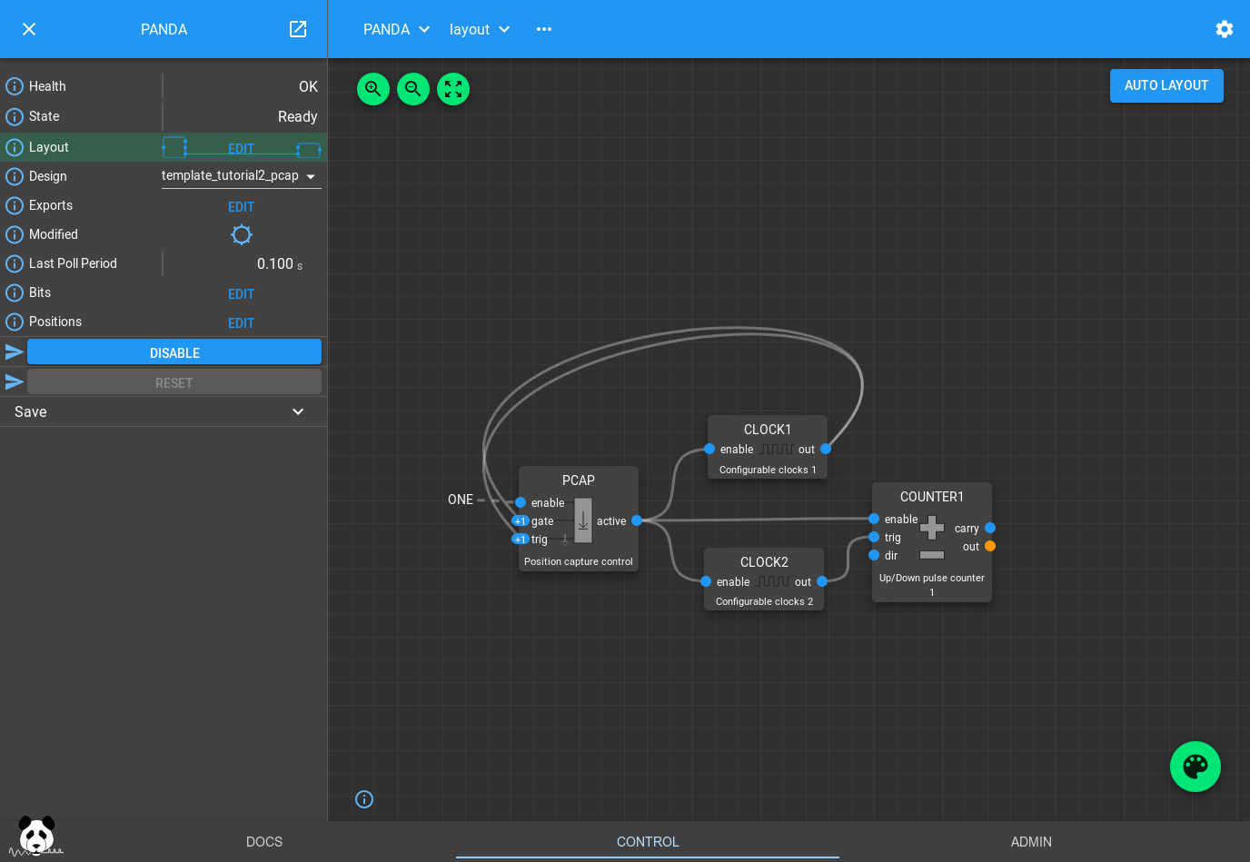
Select template_tutorial2_pcap from the Design drop-down. The block wiring will change to:
How the design works
The design has two CLOCK blocks, both enabled as soon as the PCAP block becomes active:
CLOCK1 is wired to PCAP trigger and gate.
Gate is a level-driven signal defining the capture window.
Trigger is an edge-driven signal that captures data.
PCAP.TRIG_EDGE="Falling"so capture fires on the falling edge of the trigger.
CLOCK2 is wired to a COUNTER, incrementing its value on each rising edge.
With both CLOCKs set to a 1 s period, each second the COUNTER increments by one and the PCAP trigger fires half a second later.
Timing diagram — Trigger Only (1 s clock):
         Gate:    _____|‾‾‾‾‾‾|________|‾‾‾‾‾‾|___
         Trig:    _________|__|_____________|__|___
         Capture:         ↑                ↑
The PCAP block settings and the Bits/Positions tables determine what is
captured on each trigger:
| Capture mode | Description |
|---|---|
| No | Don’t capture |
| Value | Instantaneous value at time of trigger |
| Diff | Difference in value while gate was high |
| Sum | Sum of all samples while gate was high |
| Min | Smallest value seen while gate was high |
| Max | Largest value seen while gate was high |
| Mean | Average value seen while gate was high |
| Min Max | Capture both Min and Max |
| Min Max Mean | Capture Min, Max and Mean |
For Bits you can toggle instantaneous capture on or off for each bit signal. Additional PCAP outputs (start-of-frame, end-of-frame, trigger time) can be enabled on the PCAP block itself.
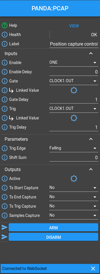
If you click the PCAP block you can see the Outputs section:
Input delays
In the Inputs section you will see a delay of 1 on both Trig and Gate. Delays on bit inputs are measured in FPGA clock ticks and compensate for different-length data paths. In this design both COUNTER1 and PCAP are triggered by CLOCK1 in the same clock tick; the 1-tick delay on PCAP inputs ensures PCAP sees the updated COUNTER1 value after the corresponding rising edge.
Capturing data
Set up Value capture
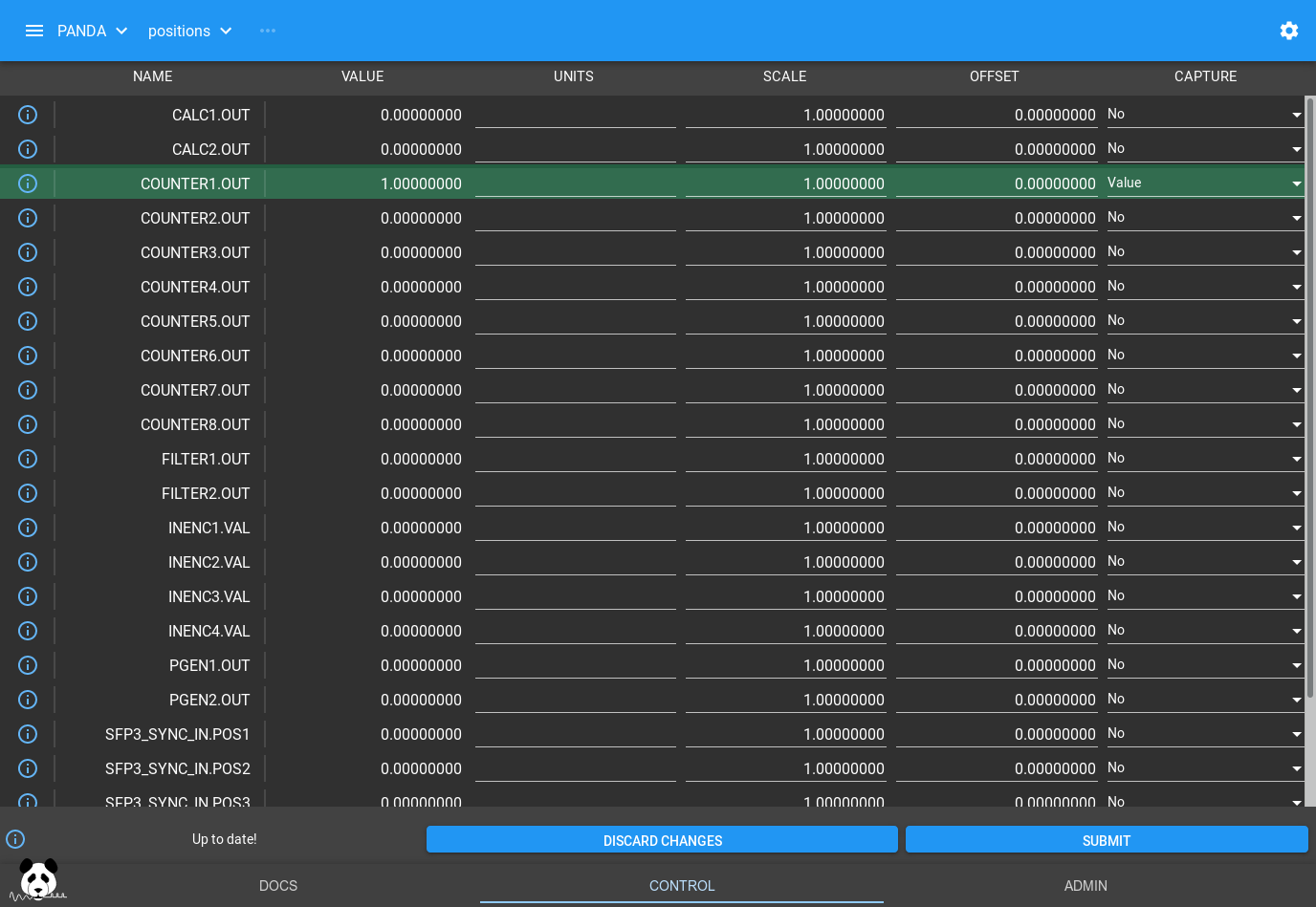
Open the Positions table and set COUNTER1.OUT to capture Value, then press Submit:
Connect a client
Open a TCP connection to port 8889 of your PandA:
$ nc <panda-ip> 8889Press Return; you should see:
OKArm and collect
Go back to the PandA layout, click the PCAP block, and press ARM. The Active indicator lights and data streams to the terminal until you press Disarm:
missed: 0
process: Scaled
format: ASCII
fields:
 COUNTER1.OUT double Value scale: 1 offset: 0 units:

 1
 2
 3
 4
END 4 Disarmed
The captured values match the instantaneous COUNTER1.OUT value at each PCAP.TRIG falling edge — consistent with the 1 s timing above.
Speed up the counter
Set CLOCK2.PERIOD to 0.2s, then ARM again:
missed: 0
process: Scaled
format: ASCII
fields:
 COUNTER1.OUT double Value scale: 1 offset: 0 units:

 3
 8
 13
 18
END 4 Disarmed
Timing diagram — Counter 5× faster:
         Counter: 0  1  2  3  4  5  6  7  8  9  10 11 12 13 14 ...
         Gate:    __|‾‾‾‾‾‾‾‾‾‾‾|___|‾‾‾‾‾‾‾‾‾‾‾|__________________
         Capture:             ↑             ↑
The value is captured mid-way through each increment of 5.
Diff capture
Change COUNTER1.OUT to capture Diff and ARM:
missed: 0
process: Scaled
format: ASCII
fields:
 COUNTER1.OUT double Diff scale: 1 offset: 0 units:

 2
 2
 2
 2
END 4 Disarmed
Diff returns the difference between the value at the gate rising edge and the
gate falling edge. Gate rises when COUNTER was at 1 and falls at 3 → diff = 2.
This capture mode is commonly used with a COUNTER connected to a V2F (voltage-to- frequency converter) to record the total counts within a gate window.
Min / Max / Mean capture
Change COUNTER1.OUT to Min Max Mean and ARM:
missed: 0
process: Scaled
format: ASCII
fields:
 COUNTER1.OUT double Min scale: 1 offset: 0 units:
 COUNTER1.OUT double Max scale: 1 offset: 0 units:
 COUNTER1.OUT double Mean scale: 1 offset: 0 units:

 1 3 1.8
 6 8 6.8
 11 13 11.8
 16 18 16.8
END 4 Disarmed
The Mean is the time-weighted average of the counter value over the gate window:
# (sum of counter_value × time_at_value) / gate_time = mean
(1×0.2 + 2×0.2 + 3×0.1) / 0.5 = 1.8
(6×0.2 + 7×0.2 + 8×0.1) / 0.5 = 6.8
This mode is useful with encoder inputs to record the min, max and mean encoder position over a detector frame.
Summary and next steps
You have used the PCAP interface to capture position data with different capture modes (Value, Diff, Min/Max/Mean), and received the ASCII stream over TCP.
The next tutorial (Tutorial 4: Position Compare) covers position compare — generating triggers automatically when an encoder reaches a set of target positions.