This tutorial introduces the basics of PandABlocks: how to wire blocks together so that different LEDs flash at different rates.
Prerequisites
A PandA powered on and reachable in your browser (see Connecting to web control).
The
template_tutorial1_ledsdesign saved on your PandA (pre-loaded on all standard PandA images).
Opening the web control
Navigate to http://<panda-hostname>/ in your browser.
The welcome page has links for Docs, Control and Admin at the bottom.
Click Control to open the web control.
Loading the tutorial design
The Design drop-down lists saved designs stored on the PandA. Selecting one replaces the current block settings with the saved ones.
Select template_tutorial1_leds from the drop-down. The blocks and wiring will change to:
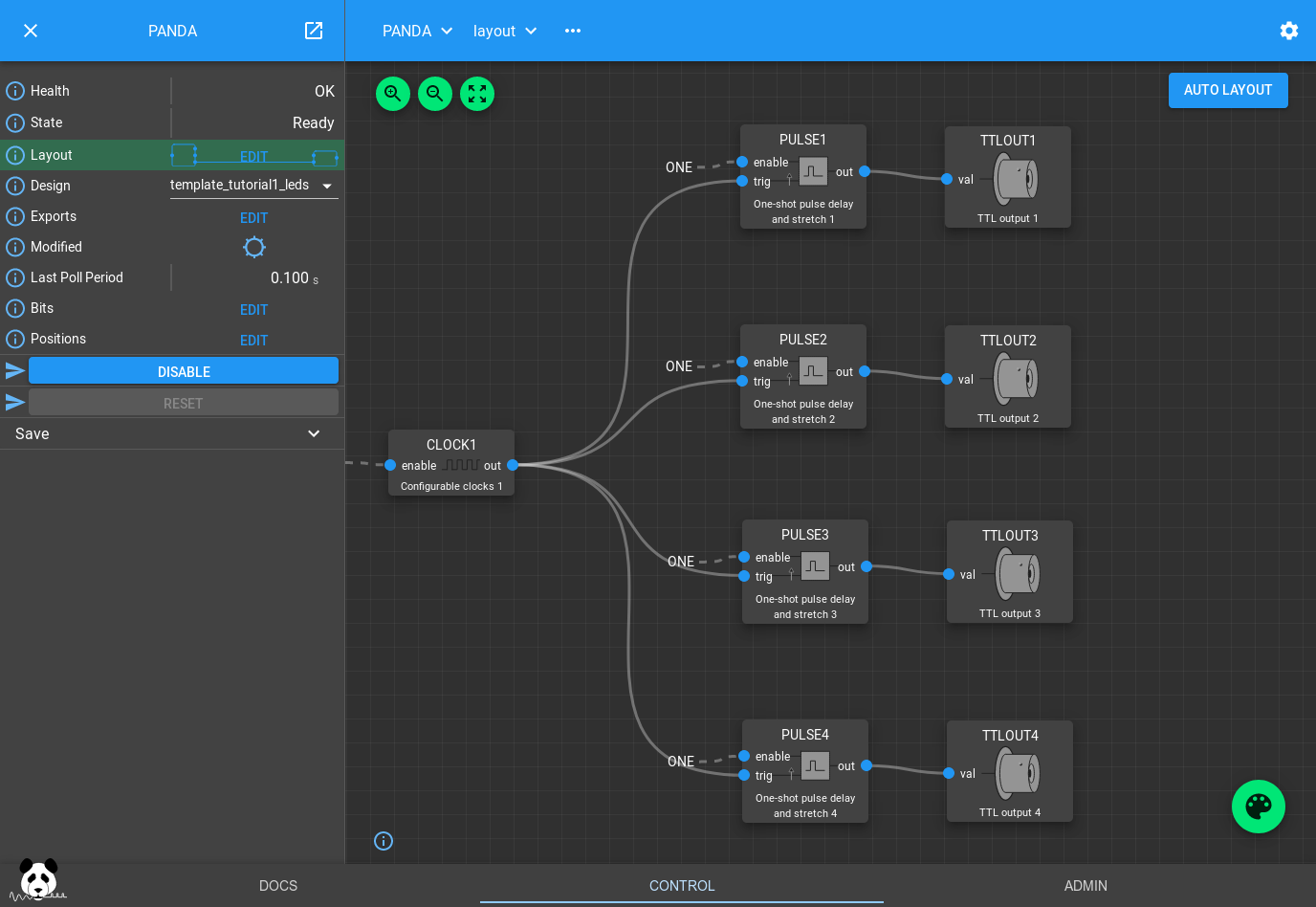
If you look at the front panel of the PandA you should see the first four TTL output LEDs turn on sequentially, then turn off in reverse order.
How the design works
The CLOCK1 block generates a 50% duty-cycle pulse train with a 1 s period. PULSE1–4 each take this as an input trigger and produce a pulse with a different width and delay. The PULSE blocks act as a delay line, queuing pulses until each delay expires.
Click on any PULSE block to see its settings:
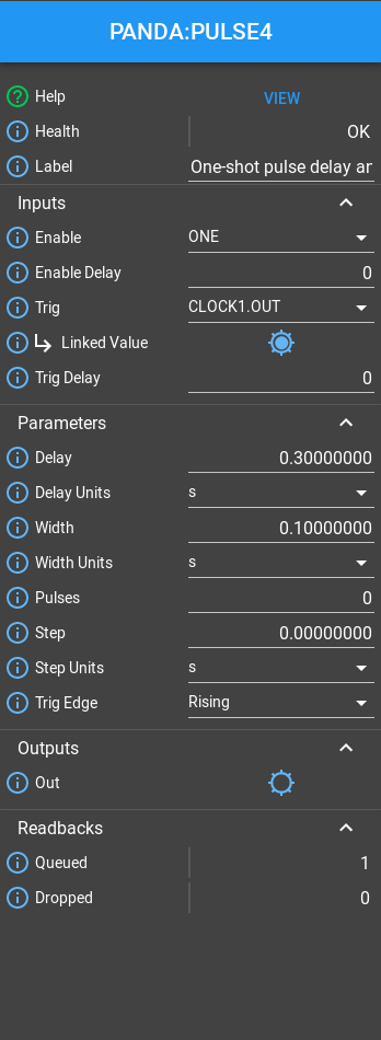
You can also click the CLOCK1 block to adjust the input pulse period.
To explore further, try wiring pulse outputs to different TTLOUT blocks: click the Palette icon, drag a TTLOUT block onto the canvas, then connect a PULSE out port to the TTLOUT val port by dragging between them.
The bit bus
All visible block ports are blue — they carry single boolean (bit) values. You can view all bit values at once by clicking Bits in the left-hand panel:
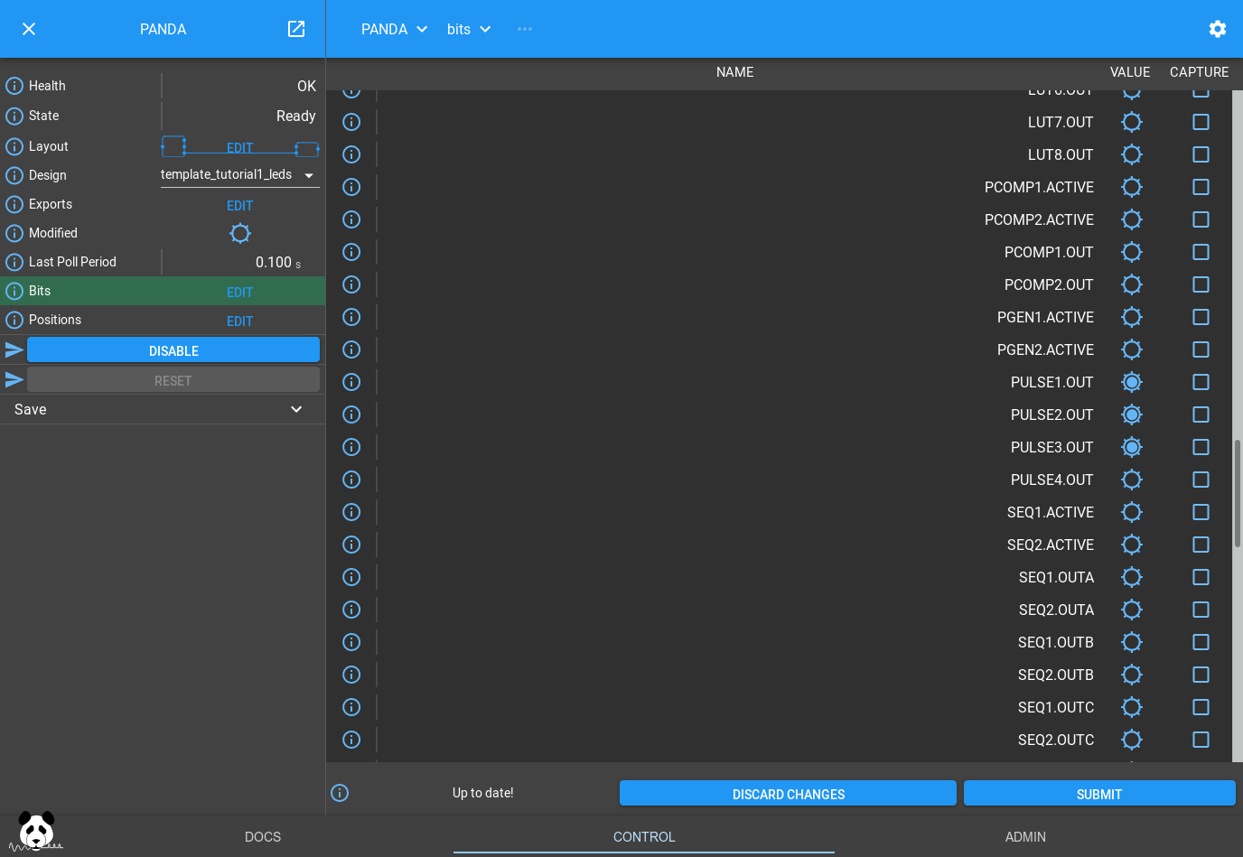
Scroll to the PULSE section to see the same flashing pattern as on the PandA front panel.
Summary and next steps
You have loaded a saved design, inspected block parameters, and seen bit outputs connected to hardware TTL outputs via TTLOUT blocks.
Continue with Tutorial 3: Position Capture to learn about position outputs and data capture.