Position capture has the capability to capture anything that is happening on the pos_bus or bit_bus. It listens to ENABLE, GATE and CAPTURE signals, and can capture the value at capture, sum, sum of squared values, min and max.
Fields
| Name | Type | Description |
|---|---|---|
| ENABLE | bit_mux | After arm, when high start capture, when low disarm |
| GATE | bit_mux | After enable, only process gated values if high |
| TRIG | bit_mux | On selected edge capture current value and gated data |
| TRIG_EDGE | param enum | Which edge of capture input signal triggers capture |
| SHIFT_SUM | param uint 8 | Shift sum/samples data, use if > 2**32 samples required in sum/average |
| ACTIVE | bit_out | Data capture in progress |
| TS_START | ext_out timestamp | Timestamp of first gate high in current capture relative to enable |
| TS_END | ext_out timestamp | Timestamp of last gate high +1 in current capture relative to enable |
| TS_TRIG | ext_out timestamp | Timestamp of capture event relative to enable |
| GATE_DURATION | ext_out samples | Number of gated samples in the current capture |
| BITS0 | ext_out bits 0 | Quadrant 0 of bit_bus |
| BITS1 | ext_out bits 1 | Quadrant 1 of bit_bus |
| BITS2 | ext_out bits 2 | Quadrant 2 of bit_bus |
| BITS3 | ext_out bits 3 | Quadrant 3 of bit_bus |
| HEALTH | read enum | Was last capture successful? |
Arming
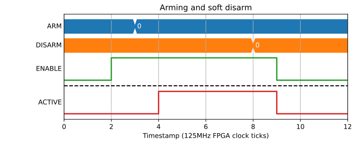
To start off the block an arm signal is required with a write to *PCAP.ARM=.
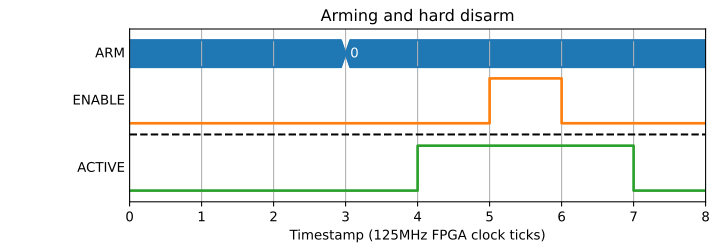
The active signal is raised immediately on ARM, and dropped either on
*PCAP.DISARM:
Or on the falling edge of ENABLE:
Capturing fields
Capturing fields is done by specifying a series of WRITE addresses. These are made up of a mode in the bottom 4 bits, and an index in the 6 bits above them. Indexes < 32 refer to entries on the pos_bus, while indexes >= 32 are extra entries specific to PCAP, like timestamps and number of gated samples. The values sent via the WRITE register are written from the TCP server, so will not be visible to end users.
Data is ticked out one at a time from the DATA attribute, then sent to the TCP server over DMA, before being sent to the user. It is reconstructed into a table in each of the examples below for ease of reading.
The following example shows PCAP being configured to capture the timestamp when CAPTURE goes high (0x24 is the bottom 32-bits of TS_CAPTURE).
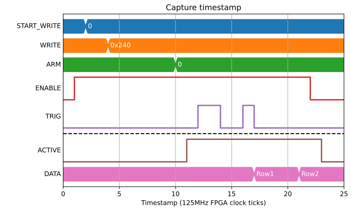
| Row | 0x240 |
|---|---|
| 0 | 2 |
| 1 | 6 |
Pos bus capture
As well as general fields like the timestamp, any pos_bus index can be captured. Pos bus fields have multiple modes that they can capture in.
Mode 0 - Value
This gives an instantaneous capture of value no matter what the state of GATE:
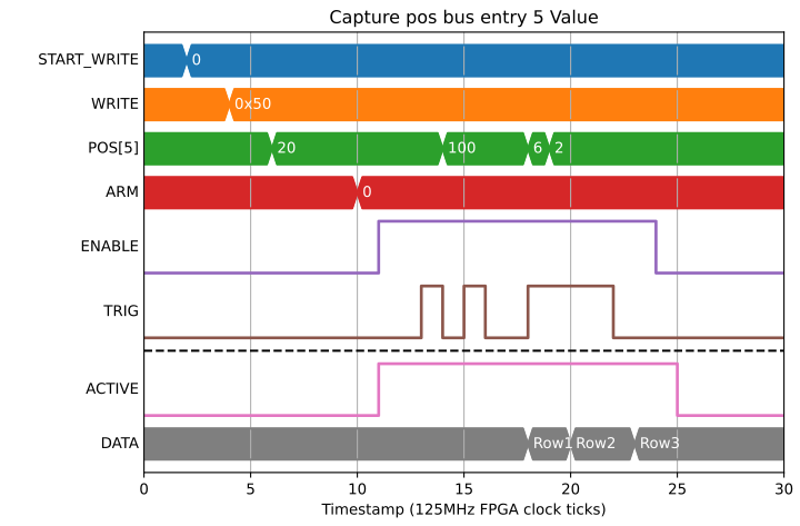
| Row | 0x50 |
|---|---|
| 0 | 20 |
| 1 | 100 |
| 2 | 6 |
Mode 1 - Difference
This is mainly used for something like an incrementing counter value. It will only count the differences while GATE was high:
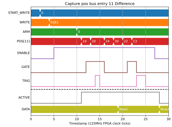
| Row | 0xB1 |
|---|---|
| 0 | 10 |
| 1 | -5 |
Mode 2/3 - Sum Lo/Hi
Mode 2 is the lower 32-bits of the sum of all samples while GATE was high:
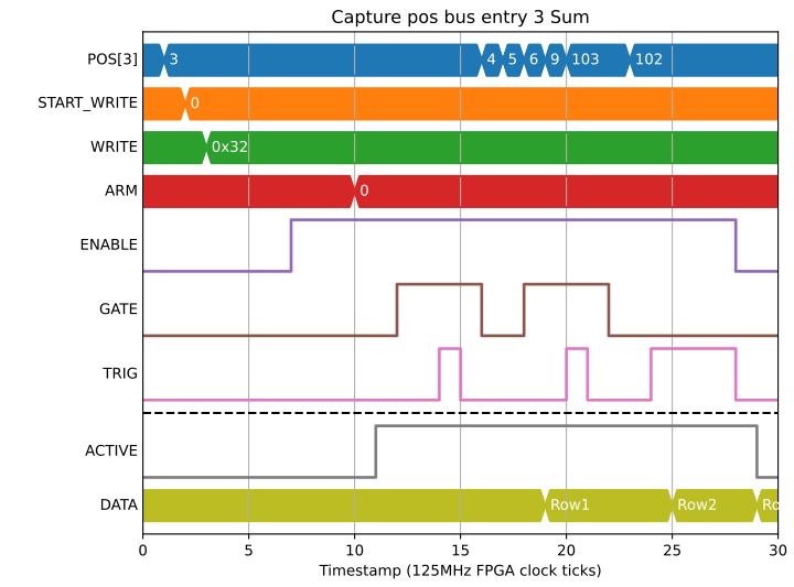
| Row | 0x32 |
|---|---|
| 0 | 6 |
| 1 | 21 |
| 2 | 206 |
Mode 2 and 3 together gives the full 64-bits of sum, needed for any sizeable values on the pos_bus:
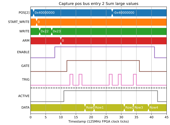
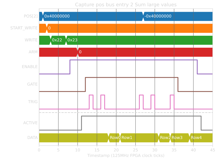
| Row | 0x22 | 0x23 |
|---|---|---|
| 0 | 1073741824 | 0 |
| 1 | -1073741824 | 0 |
| 2 | -2147483648 | 2 |
| 3 | -1073741824 | -1 |
| 4 | -1073741824 | -2 |
If long frame times (> 2**32 SAMPLES, > 30s), are to be used, then SHIFT_SUM can be used to shift both the sum and SAMPLES field by up to 8-bits to accomodate up to 125 hour frames. This example demonstrates the effect with smaller numbers:
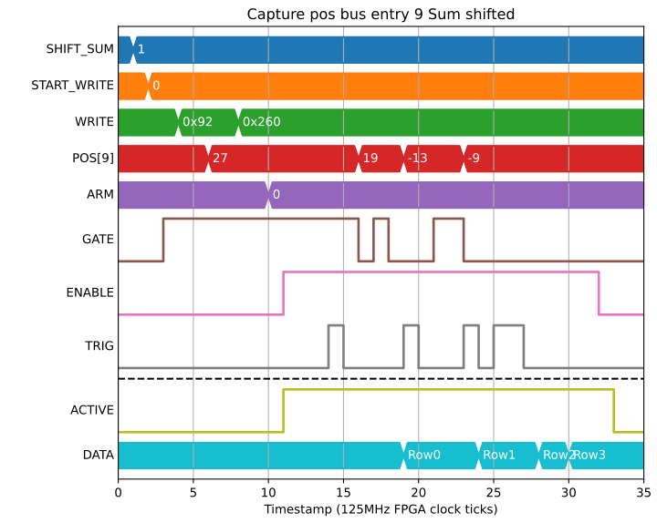
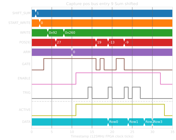
| Row | 0x92 | 0x260 |
|---|---|---|
| 0 | 40 | 1 |
| 1 | 36 | 1 |
| 2 | -13 | 1 |
| 3 | 0 | 0 |
Mode 4/5 - Min/Max
Both of these modes calculate statistics on the value while GATE is high.
Mode 4 produces the min of all values or zero if the gate was low for all of the current capture:
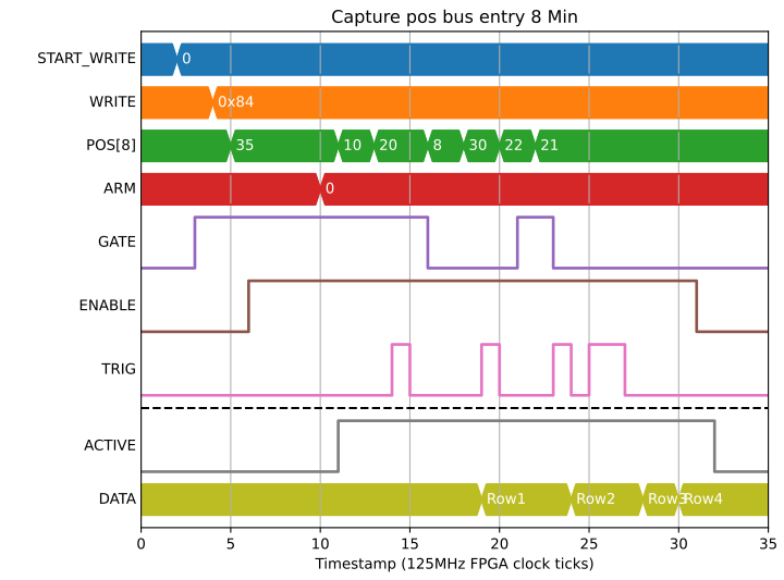
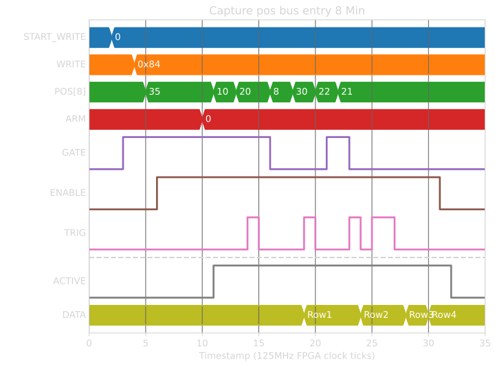
| Row | 0x84 |
|---|---|
| 0 | 10 |
| 1 | 20 |
| 2 | 21 |
| 3 | 2147483647 |
Mode 5 produces the max of all values in a similar way:
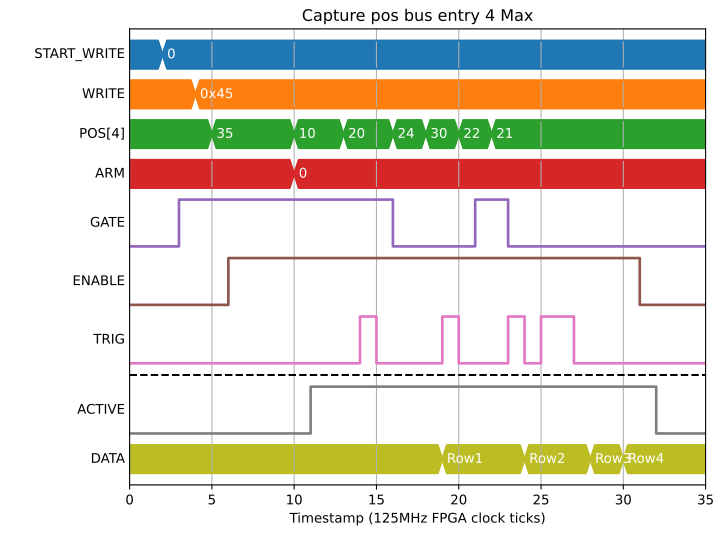
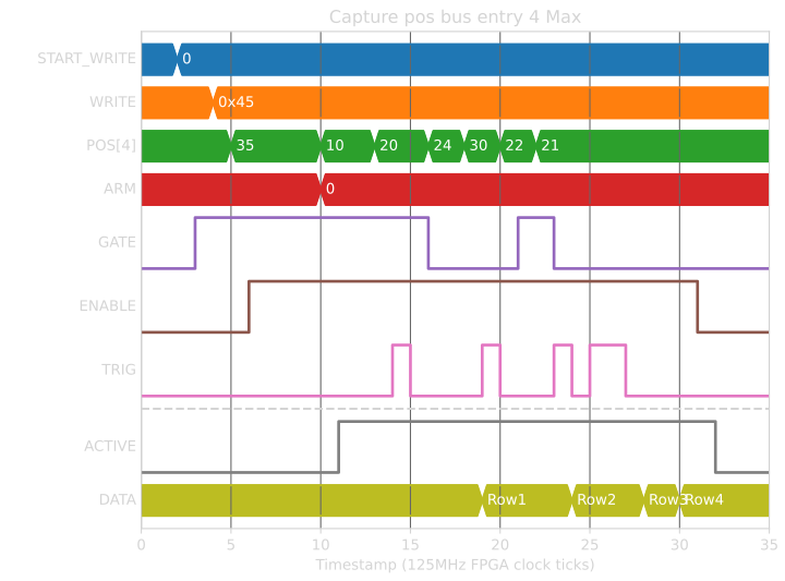
| Row | 0x45 |
|---|---|
| 0 | 20 |
| 1 | 20 |
| 2 | 22 |
| 3 | -2147483648 |
Mode 6/7/8 - Sum of Squared values Lo/Mid/Hi
Mode 6/7/8 is only implemented when target supports pcap_std_dev fpga option.
Mode 6, 7 and 8 together gives the full 96-bits of sum of squared values needed for any sizeable values on the pos_bus.
Mode 6 is the lower 32-bits while GATE was high, Mode 7 is the middle 32-bits, and Mode 8 is the higher 32-bits:
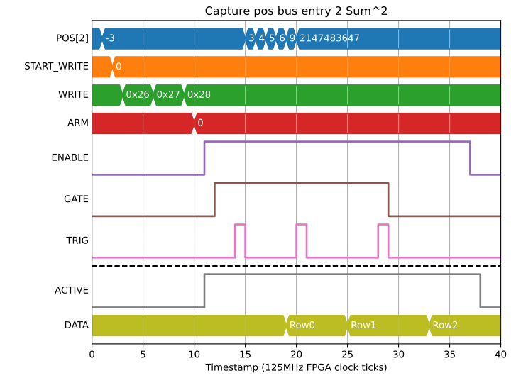
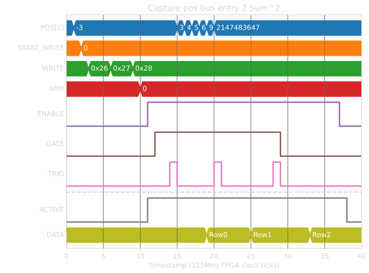
| Row | 0x26 | 0x27 | 0x28 |
|---|---|---|---|
| 0 | 18 | 0 | 0 |
| 1 | 176 | 0 | 0 |
| 2 | 8 | 4294967288 | 1 |
If long frame times (> 2**32 SAMPLES, > 30s), are to be used, then SHIFT_SUM can be used to shift both the sum of squared values and SAMPLES field by up to 8-bits to accomodate up to 125 hour frames:
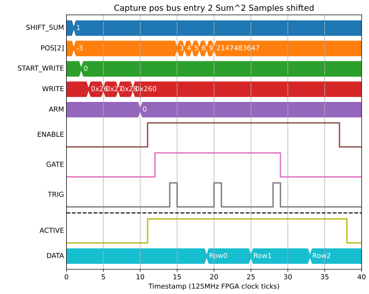
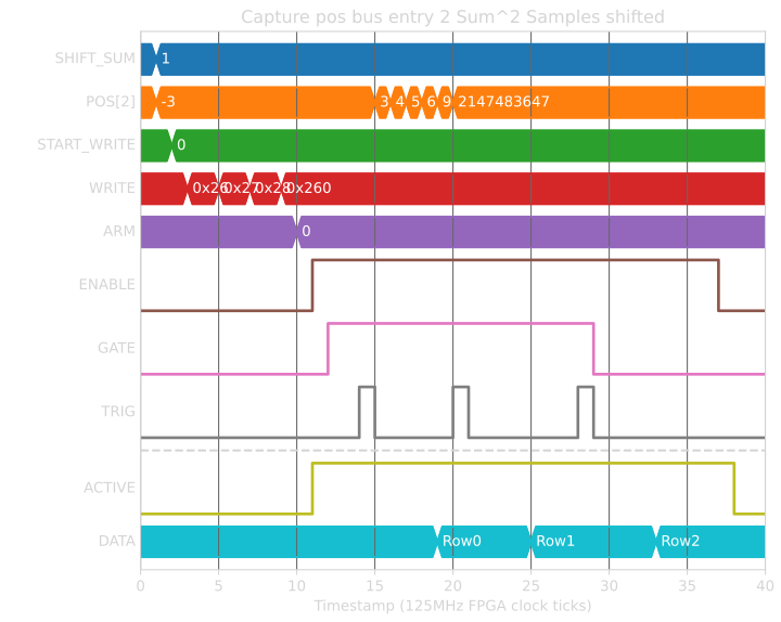
| Row | 0x26 | 0x27 | 0x28 | 0x260 |
|---|---|---|---|---|
| 0 | 9 | 0 | 0 | 1 |
| 1 | 88 | 0 | 0 | 3 |
| 2 | 4 | 4294967292 | 0 | 4 |
Number of samples
There is a SAMPLES field that can be captured that will give the number of clock ticks that GATE was high during a single CAPTURE. This field allows the TCP server to offer “Mean” as a capture option, dividing “Sum” by SAMPLES to get the mean value of the field during the capture period. It can also be captured separately to give the gate length:
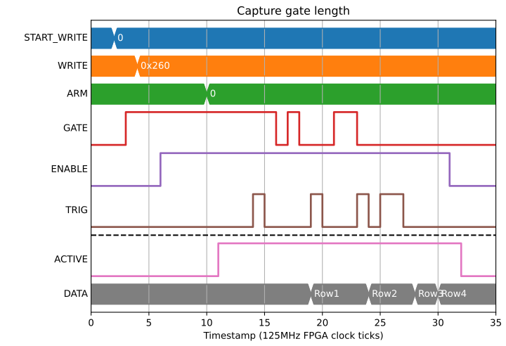
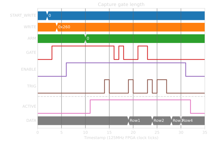
| Row | 0x260 |
|---|---|
| 0 | 4 |
| 1 | 3 |
| 2 | 2 |
| 3 | 0 |
Timestamps
As well as the timestamp of the capture signal, timestamps can also be generated for the start of each capture period (first gate high signal) and end (the tick after the last gate high). These are again split into two 32-bit segments so only the lower bits need to be captured for short captures. In the following example we capture TS_START (0x20), TS_END (0x22) and TS_CAPTURE (0x24) lower bits:
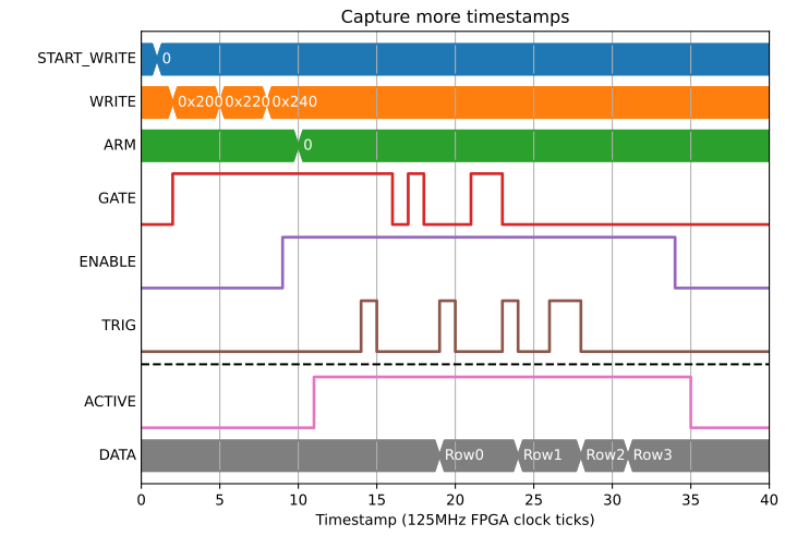
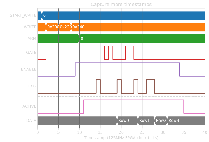
| Row | 0x200 | 0x220 | 0x240 |
|---|---|---|---|
| 0 | 0 | 4 | 4 |
| 1 | 4 | 8 | 9 |
| 2 | 11 | 13 | 13 |
| 3 | -1 | -1 | 16 |
Bit bus capture
The state of the bit bus at capture can also be captured. It is split into 4 quadrants of 32-bits each. For example, to capture signals 0..31 on the bit bus we would use BITS0 (0x27):
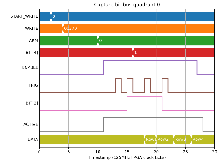
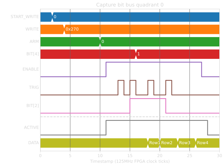
| Row | 0x270 |
|---|---|
| 0 | 0 |
| 1 | 4 |
| 2 | 20 |
| 3 | 16 |
By capturing all 4 quadrants (0x27..0x2A) we get the whole bit bus:
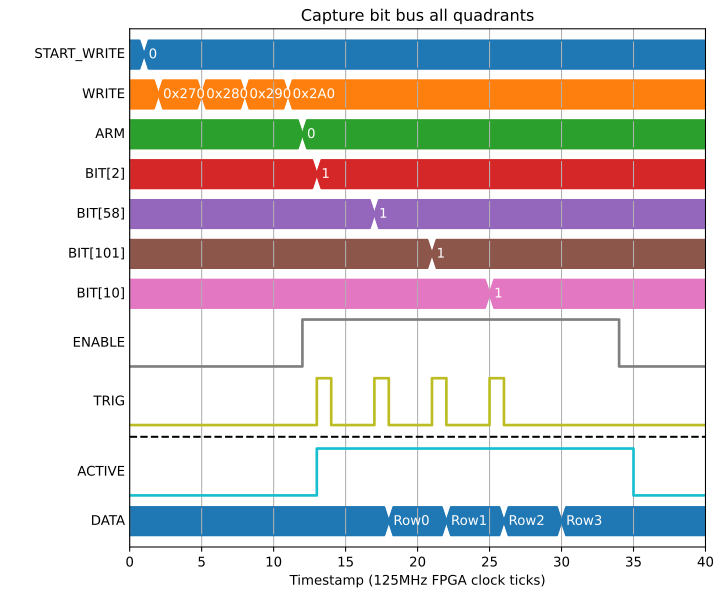
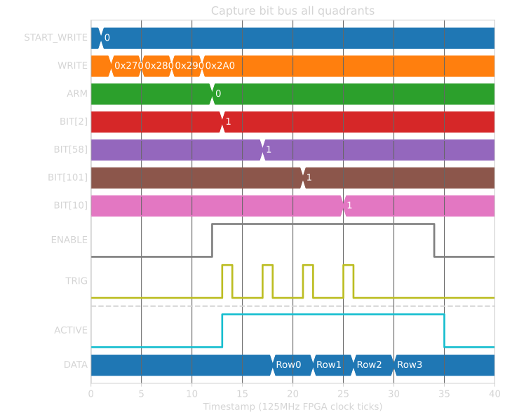
| Row | 0x270 | 0x280 | 0x290 | 0x2A0 |
|---|---|---|---|---|
| 0 | 4 | 0 | 0 | 0 |
| 1 | 4 | 67108864 | 0 | 0 |
| 2 | 4 | 67108864 | 0 | 32 |
| 3 | 1028 | 67108864 | 0 | 32 |
Triggering options
ENABLE and GATE are level triggered, with ENABLE used for marking the start and end of the entire acquisition, and GATE used to accept or reject samples within a single capture from the acquisition. CAPTURE is edge triggered with an option to trigger on rising, falling or both edges.
Triggering on rising is the default, explored in the preceding examples. Triggering on falling edge would be used if you have a gate signal that marks the capture boundaries and want sum or difference data within. For example, to capture the amount POS[1] changes in each capture gate we could connect GATE and CAPTURE to the same signal:
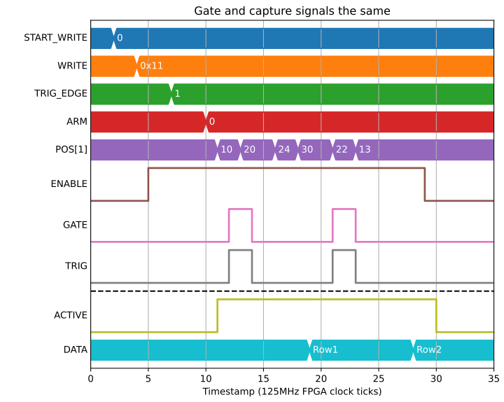
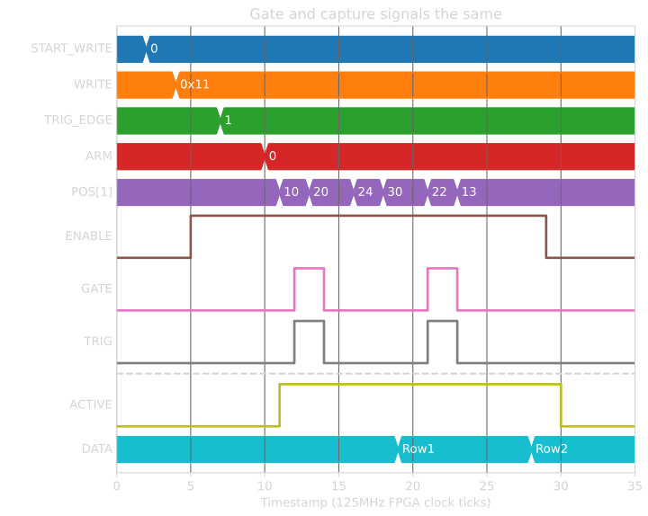
| Row | 0x11 |
|---|---|
| 0 | 10 |
| 1 | -9 |
Another option would be a gap-less acquisition of sum while gate is high with capture boundaries marked with a toggle of CAPTURE:
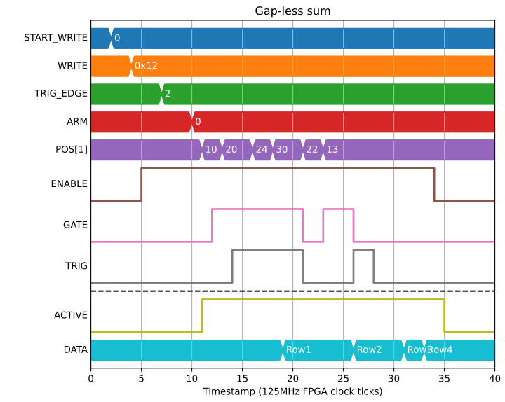
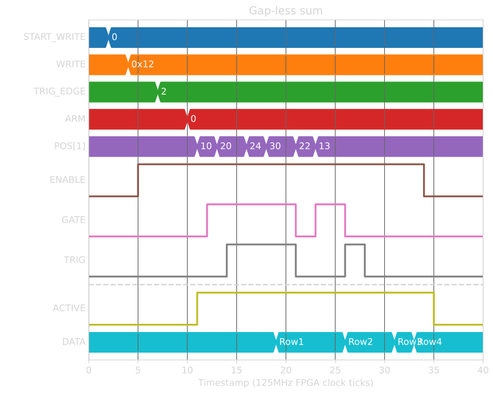
| Row | 0x12 |
|---|---|
| 0 | 30 |
| 1 | 178 |
| 2 | 39 |
| 3 | 0 |
Error conditions
The distance between capture signals must be at least the number of 32-bit capture fields. If 2 capture signals are too close together HEALTH will be set to 1 (Capture events too close together).
In this example there are 3 fields captured (TS_CAPTURE_L, TS_CAPTURE_H, SAMPLES), but only 2 clock ticks between the 2nd and 3rd capture signals:
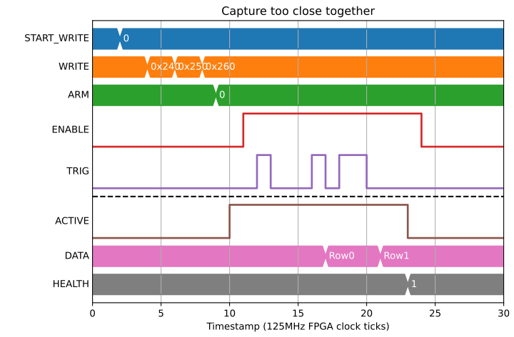
| Row | 0x240 | 0x250 | 0x260 |
|---|---|---|---|
| 0 | 1 | 0 | 0 |
| 1 | 5 | 0 | 0 |