The POSENC block handles the Quadrature and step/direction encoding
Fields
| Name | Type | Description |
|---|---|---|
| ENABLE | bit_mux | Halt on falling edge, reset and enable on rising |
| INP | pos_mux | Output position |
| PERIOD | param time | Minimum time between Quadrature transitions of step pulses |
| PROTOCOL | param enum | Quadrature or step/direction |
| A | bit_out | Quadrature A/Step output |
| B | bit_out | Quadrature B/Direction output |
| STATE | read enum | State of quadrature output |
Quadrature
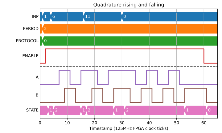
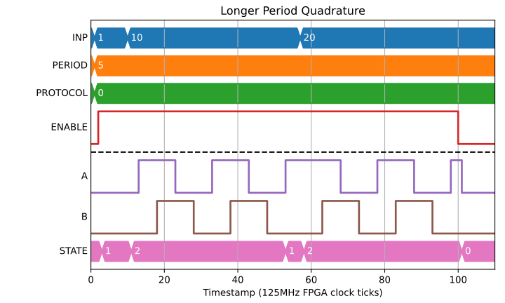
When in the quadrature mode, the module will output signals A and B in different states as it counts up or down. When counting up B will follow A and when counting down A will follow B. The period is the time between an edge on one signal to the next edge of the other signal.
The input is initially set as the value of the INP line when ENABLE goes high. The system will then count to the current value on the INP line, and when it reaches this value the output signals will stay as they are.
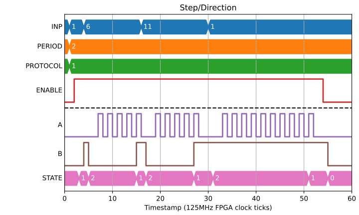
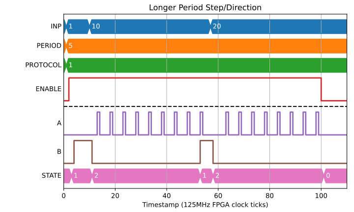
The state output is ‘0’ while ENABLE is low, ‘1’ when the count is equal to the signal on the INP line and ‘2’ while it is counting towards the INP value.
Step/Direction
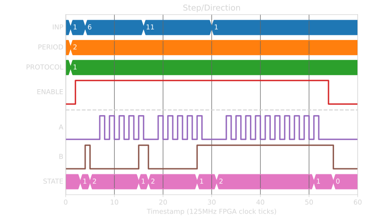
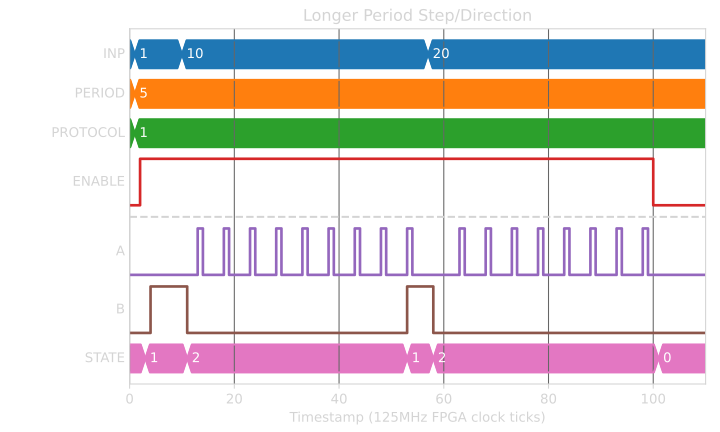
In the Step/Direction mode the A output becomes a step output. This goes high on every period for one clock cycle and is low for the remainder of the period. The B output becomes the direction output, it is ‘0’ when the internal counter is lower than the inputted target value (it is counting up), and ‘1’ when it is greater or equal to.