LUT - 5 Input lookup table
An LUT block produces an output that is determined by a user-programmable 5-input logic function, set with the FUNC register.
Fields
Name |
Type |
Description |
|---|---|---|
INPA |
bit_mux |
Input A |
INPB |
bit_mux |
Input B |
INPC |
bit_mux |
Input C |
INPD |
bit_mux |
Input D |
INPE |
bit_mux |
Input E |
TYPEA |
param enum |
Source of the value of A for calculation
0 Input-Level
1 Pulse-On-Rising-Edge
2 Pulse-On-Falling-Edge
3 Pulse-On-Either-Edge
|
TYPEB |
param enum |
Source of the value of B for calculation
0 Input-Level
1 Pulse-On-Rising-Edge
2 Pulse-On-Falling-Edge
3 Pulse-On-Either-Edge
|
TYPEC |
param enum |
Source of the value of C for calculation
0 Input-Level
1 Pulse-On-Rising-Edge
2 Pulse-On-Falling-Edge
3 Pulse-On-Either-Edge
|
TYPED |
param enum |
Source of the value of D for calculation
0 Input-Level
1 Pulse-On-Rising-Edge
2 Pulse-On-Falling-Edge
3 Pulse-On-Either-Edge
|
TYPEE |
param enum |
Source of the value of E for calculation
0 Input-Level
1 Pulse-On-Rising-Edge
2 Pulse-On-Falling-Edge
3 Pulse-On-Either-Edge
|
FUNC |
param lut |
Input func |
OUT |
bit_out |
Lookup table output |
Testing Function Output
This set of tests sets the function value and checks whether the output is as expected
The value of FUNC is a 32-bit unsigned int representing the truth table output of the 5 inputs. The mapping of the string to an integer is done by the PandABlocks TCP server.
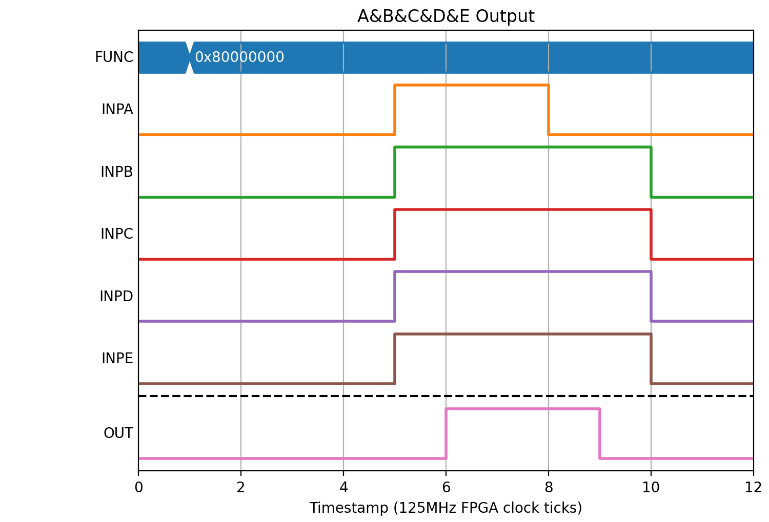
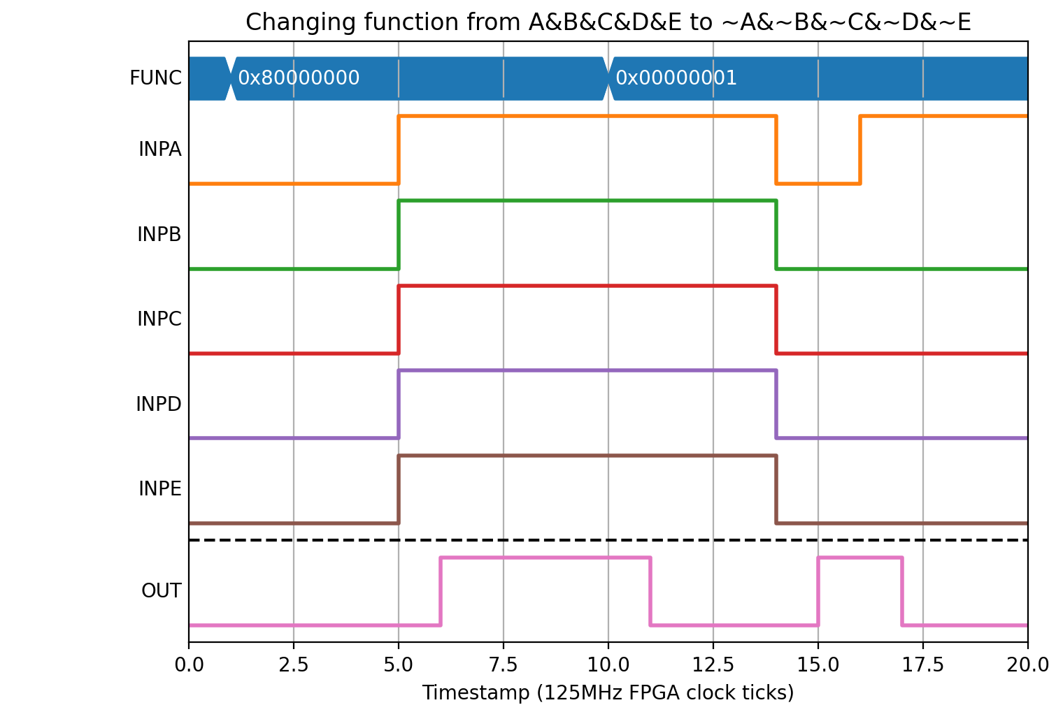
A&B&C&D&E (FUNC= 0x80000000). Setting all inputs to 1 results in an output of 1, and changing any inputs produces an output of 0
(Source code, png, hires.png, pdf)

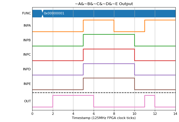
~A&~B&~C&~D&~E (FUNC= 0x00000001). Setting all inputs to 0 results in an output of 1, and changing any inputs produces an output of 0
(Source code, png, hires.png, pdf)
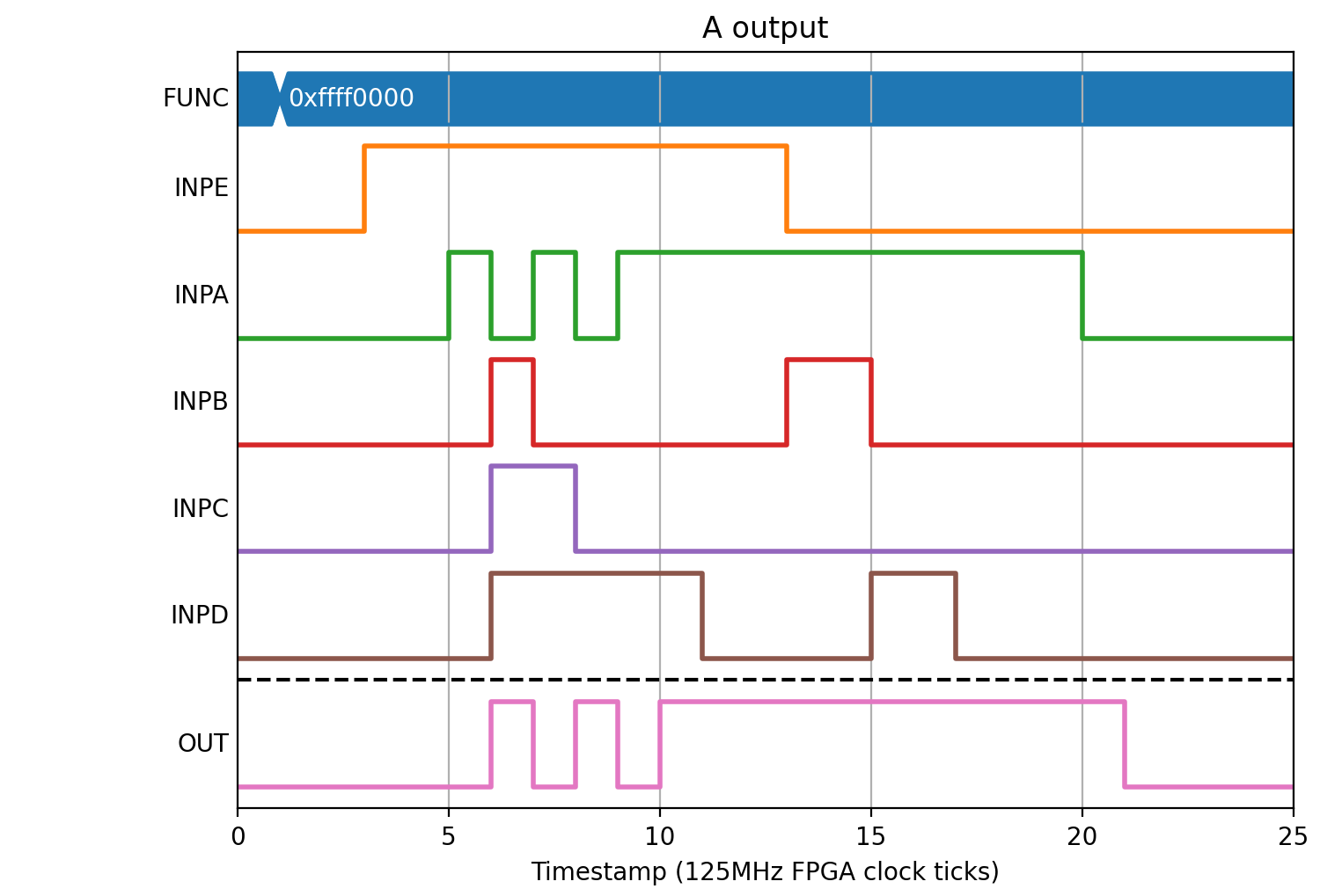
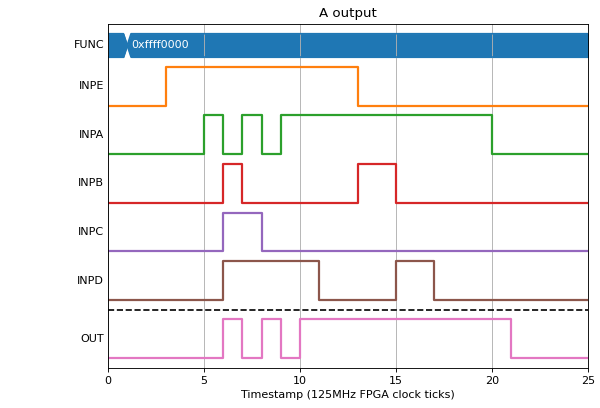
A (FUNC= 0xffff0000). The output should only be 1 if A is 1 irrespective of any other input.
(Source code, png, hires.png, pdf)
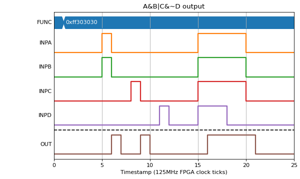
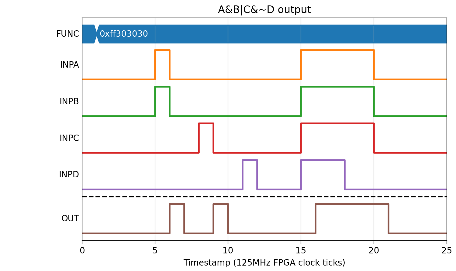
A&B|C&~D (FUNC= 0xff303030)
(Source code, png, hires.png, pdf)

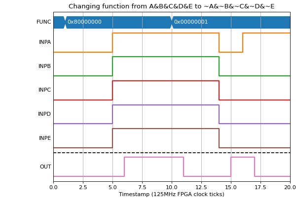
Changing the function in a test
If a function is changed, the output will take effect on the next clock tick
(Source code, png, hires.png, pdf)
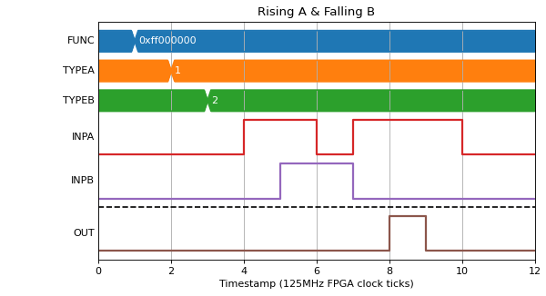
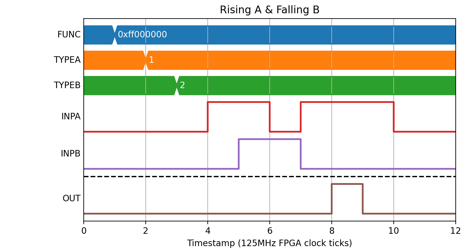
Edge triggered inputs
We can also use the LUT to convert edges into levels by changing A..E to be one clock tick wide pulses based on edges rather than the current level of INPA..INPE.
If we wanted to produce a pulse only if INPA had a rising edge on the same clock tick as INPB had a falling edge we could set FUNC=0xff000000 (A&B) and A=1 (rising edge of INPA) and B=2 (falling edge of INPB):
(Source code, png, hires.png, pdf)

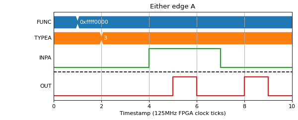
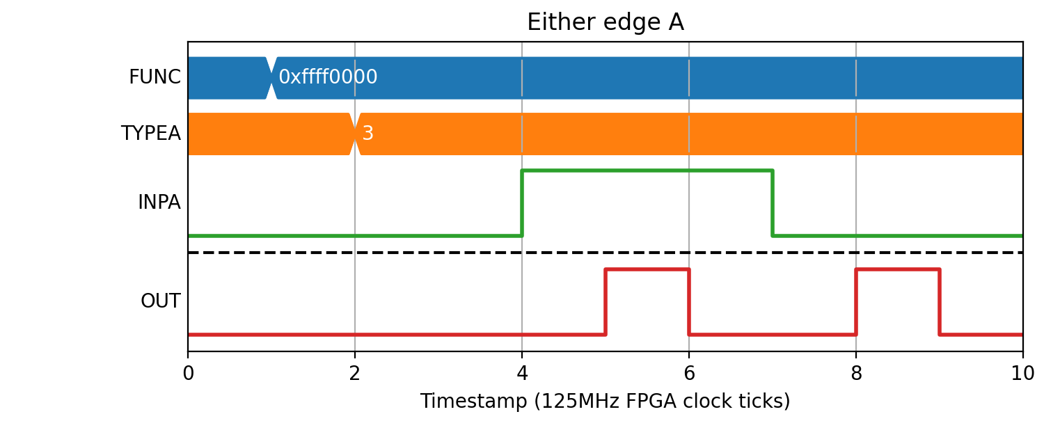
We could also use this for generating pulses on every transition of A:
(Source code, png, hires.png, pdf)