PULSE - One-shot pulse delay and stretch
A PULSE block produces configurable width output pulses with an optional delay based on its parameters. It operates in one of two modes:
If WIDTH=0, then it acts as a delay line. The input pulse train will just be replayed after the given DELAY
If WIDTH is non-zero, then each pulse edge that matches TRIG_EDGE will be delayed by the specified DELAY, then generate NPULSES pulses of width WIDTH, with rising edges separated by STEP
Fields
Name |
Type |
Description |
|---|---|---|
ENABLE |
bit_mux |
Reset on falling edge, enable on rising |
TRIG |
bit_mux |
Input pulse train |
DELAY |
time |
Output pulse delay (0 for no delay) |
WIDTH |
time |
Output pulse width (0 for input pulse width) |
PULSES |
param |
The number of pulses to produce on each trigger, 0 means 1 |
STEP |
time |
If pulses > 1, the time between successive pulse rising edges |
TRIG_EDGE |
param enum |
INP trigger edge
0 Rising
1 Falling
2 Either
|
OUT |
bit_out |
Output pulse train |
QUEUED |
read uint 1023 |
Length of the delay queue |
DROPPED |
read |
Number of pulses not produced because of an ERR condition |
Delay line
If WIDTH=0, then the Block acts as a delay line. DELAY must either be 0 or 5+ clock ticks. TRIG_EDGE, STEP, and NPULSES are ignored.
If DELAY=0 the Block is a simple pass through:
(Source code, png, hires.png, pdf)
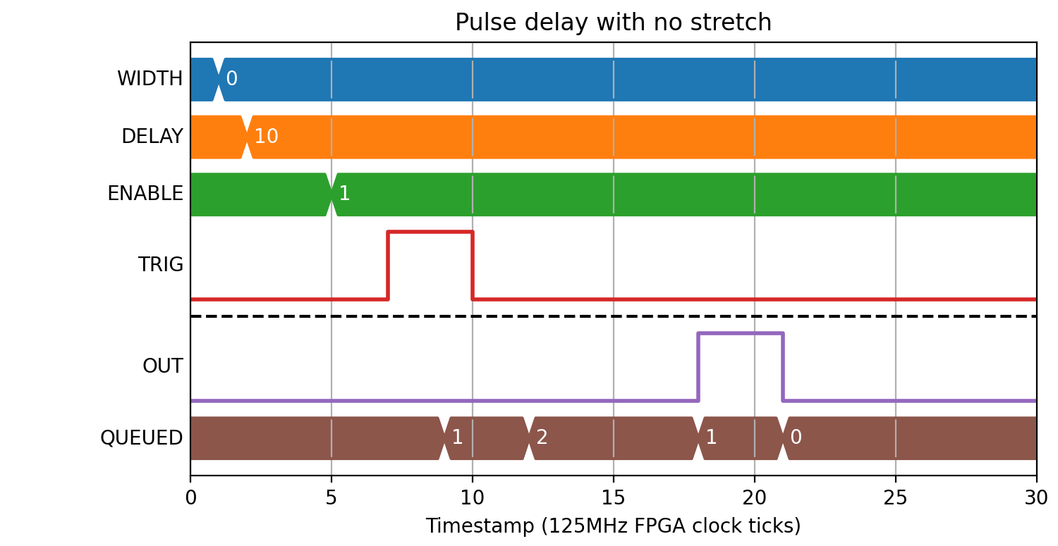
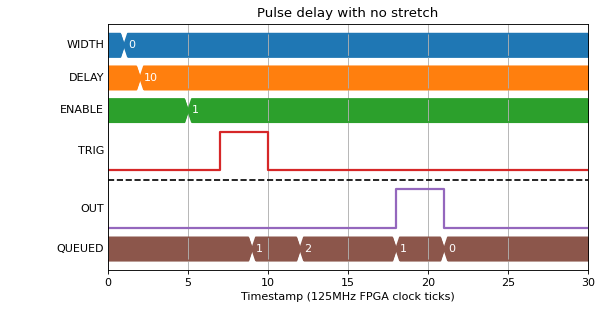
If DELAY is non-zero, rising and falling edges will be inserted in the queue and output after the given DELAY:
(Source code, png, hires.png, pdf)
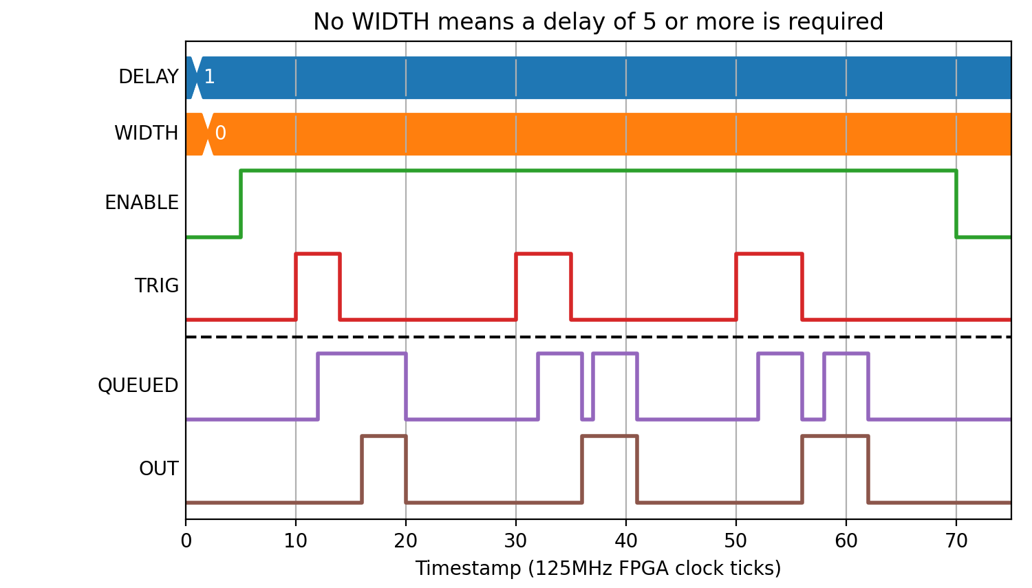
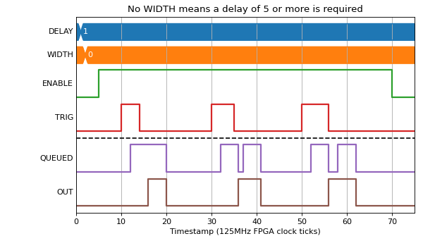
0 < DELAY < 5 will be treated as DELAY=5:
(Source code, png, hires.png, pdf)
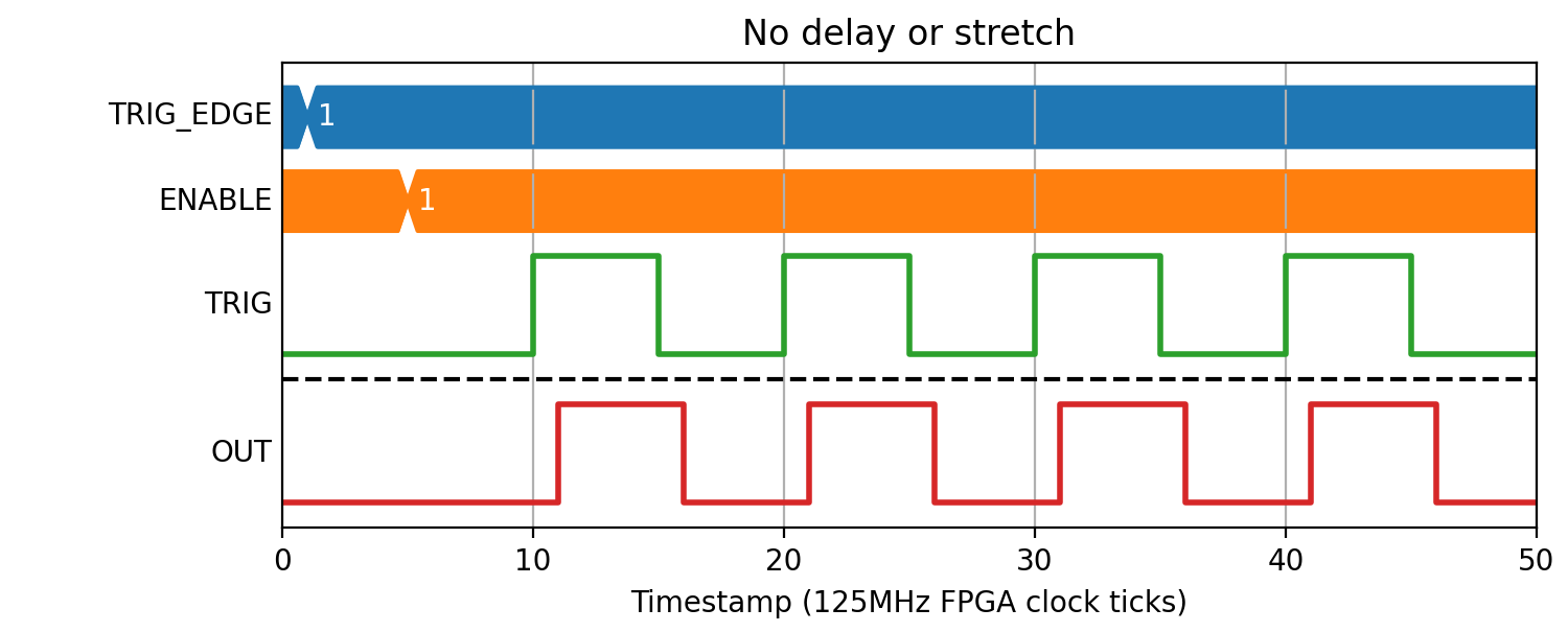
Pulse train generation
If WIDTH != 0 then the Block will operate in pulse train mode. If NPULSES is 0 or 1 then it will produce a single pulse for each matching input pulse:
(Source code, png, hires.png, pdf)

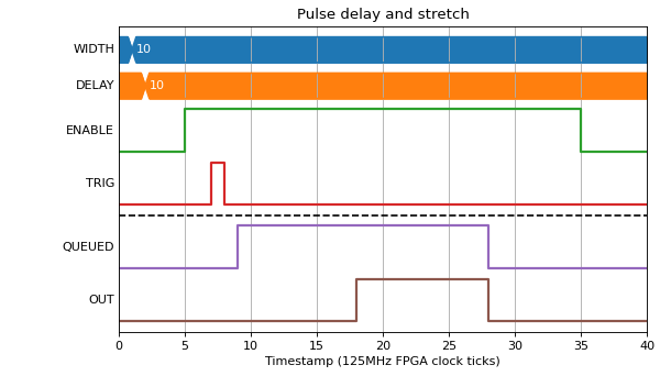
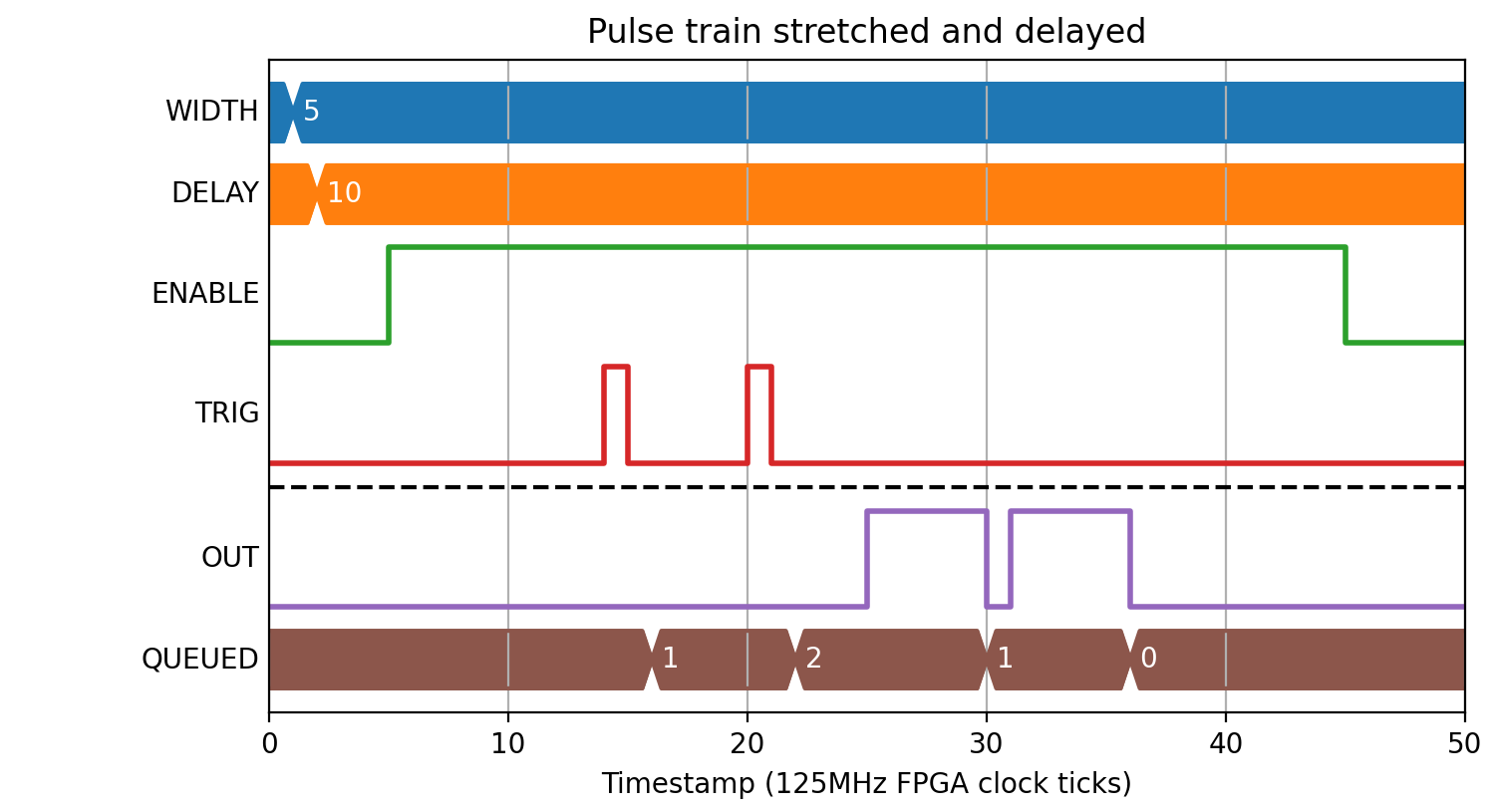
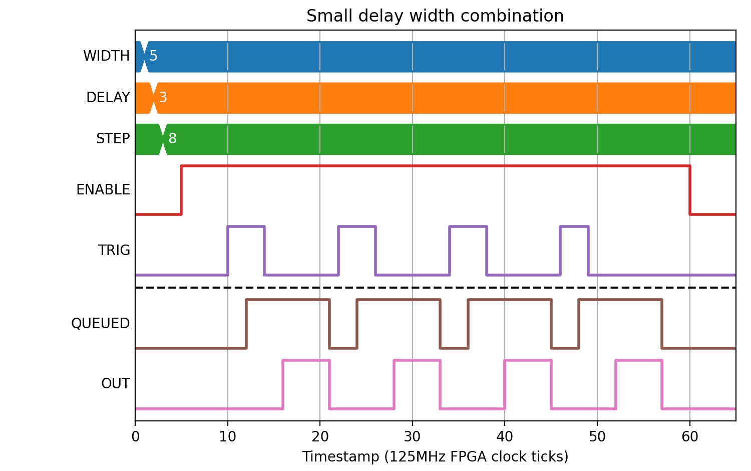
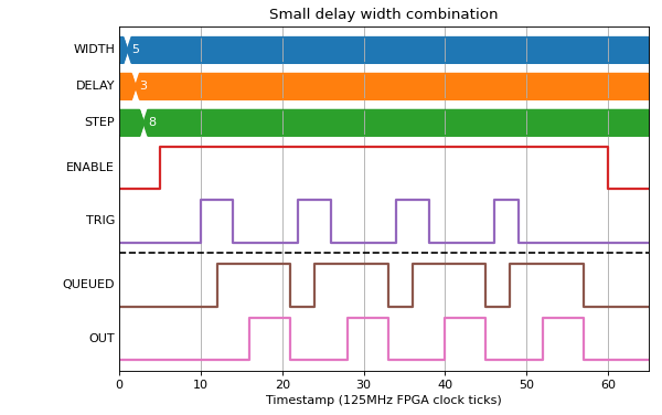
The output pulses are queued, so multiple pulses can be queued before output:
(Source code, png, hires.png, pdf)

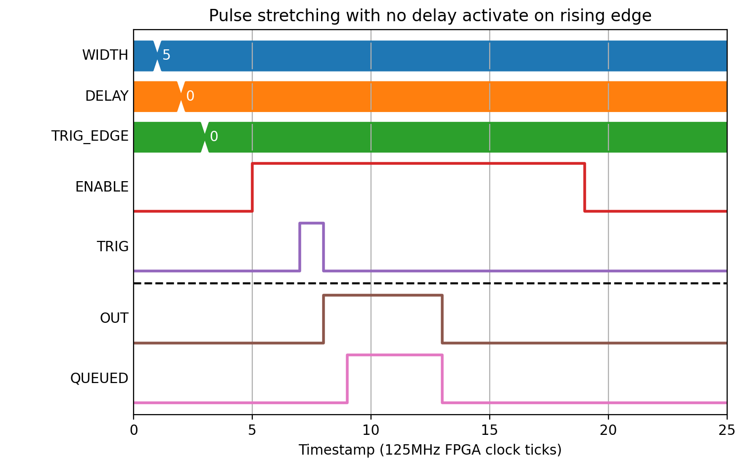
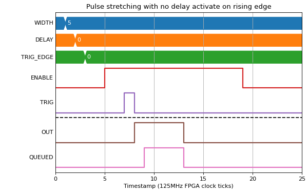
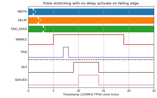
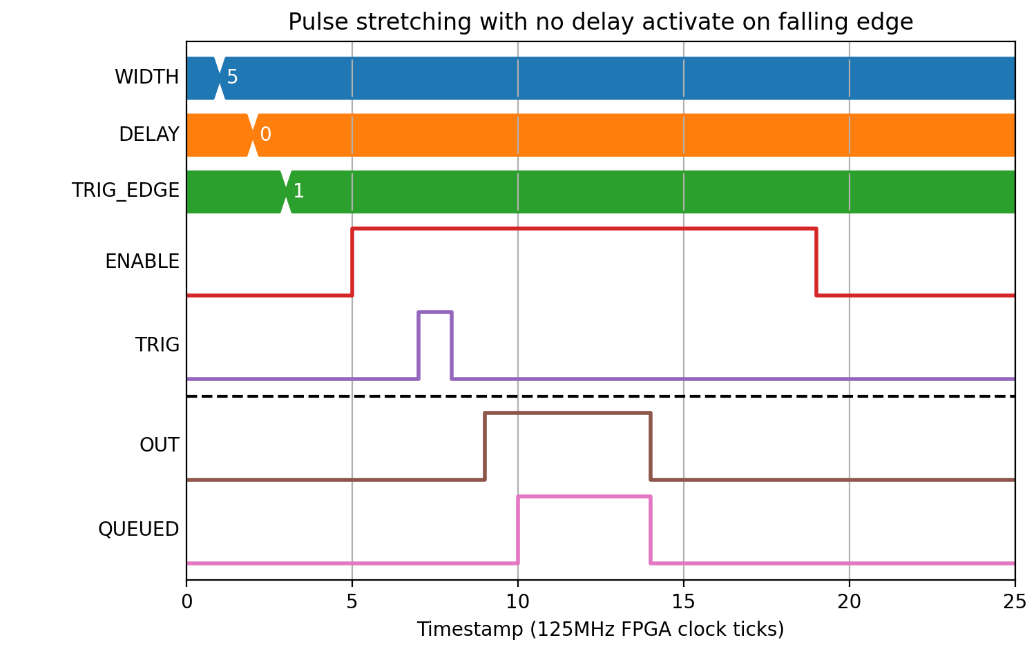
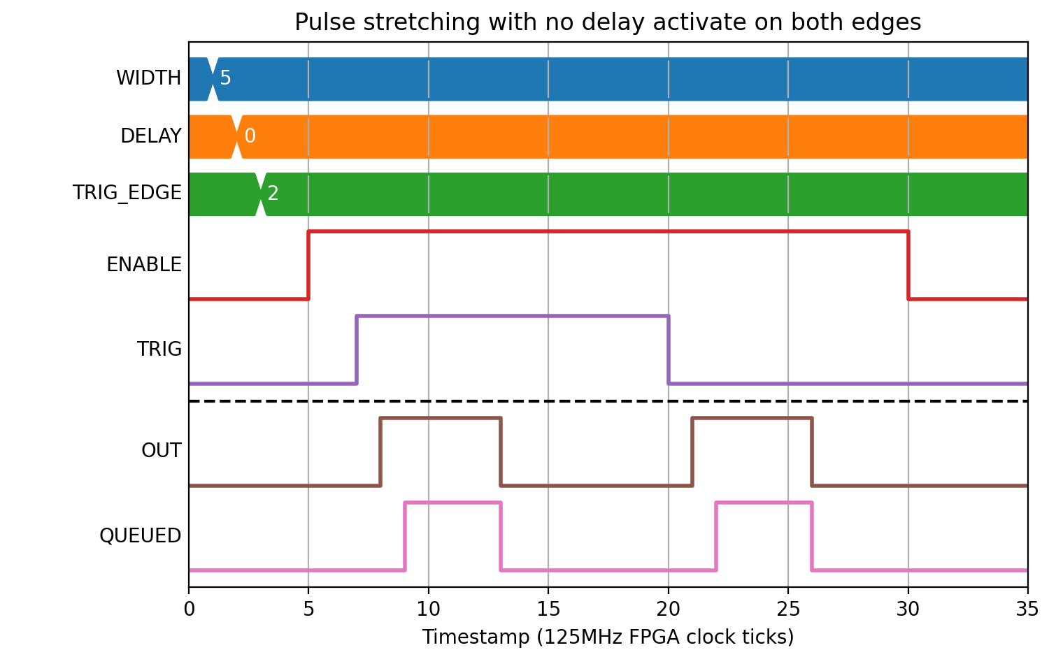
The TRIG_EDGE field can be used to select whether an input pulse queues an output on rising, falling, or both edges:
(Source code, png, hires.png, pdf)
(Source code, png, hires.png, pdf)

(Source code, png, hires.png, pdf)

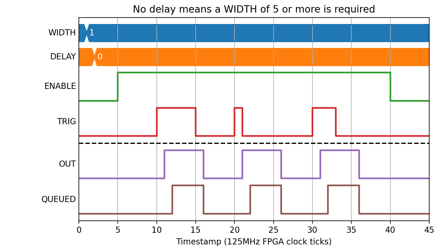
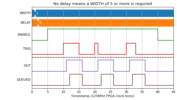
0 < WIDTH < 5 will be treated as WIDTH=5:
(Source code, png, hires.png, pdf)
If PULSES > 1 then multiple output pulses will be generated, separated by STEP:
(Source code, png, hires.png, pdf)

(Source code, png, hires.png, pdf)
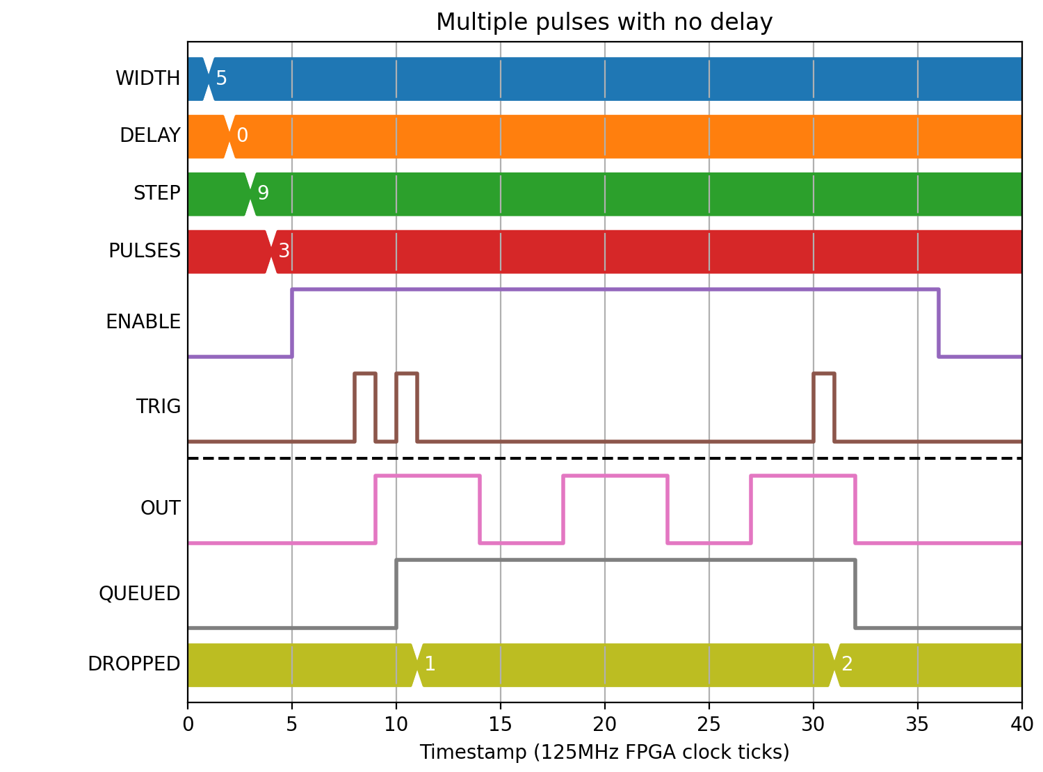
Pulse period error
The following example shows what happens when the period between pulses is too short. To avoid running output pulses together, the DROPPED field is incremented and the input is dropped:
(Source code, png, hires.png, pdf)
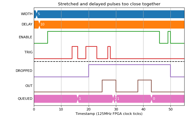
The queue length is 255, so if QUEUED reaches 255 then any new pulse will be dropped and also increment DROPPED.
The DROPPED count is zeroed on rising edge of ENABLE.
Enabling the Block
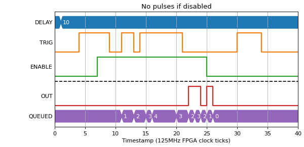
There is an Enable signal that stops the Block from producing signals. Edges must occur while Enable is high to trigger a pulse creation
(Source code, png, hires.png, pdf)
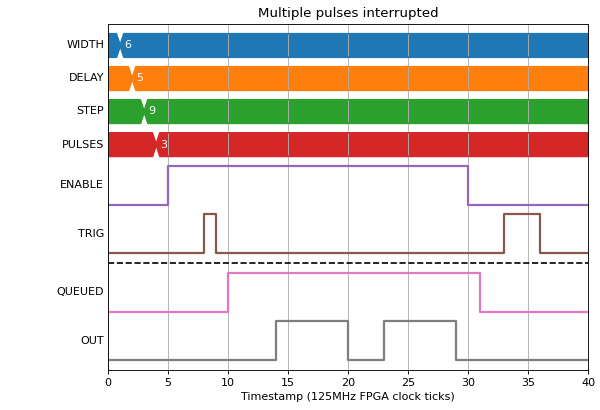
If enable is dropped mid way through a pulse train, the output is set low and the QUEUED output is set to zero.
(Source code, png, hires.png, pdf)
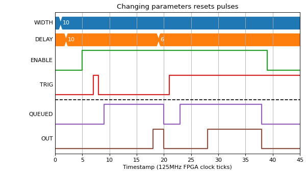
Changing parameters while Enabled
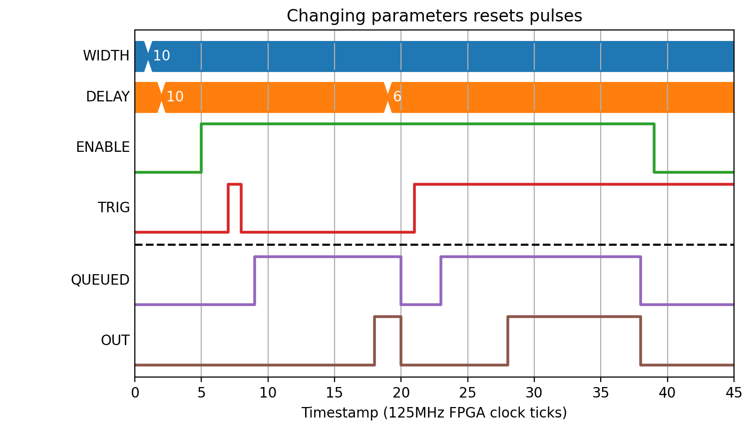
If any of the input parameters are changed while enabled, the queue is dropped and the state of the Block is reset:
(Source code, png, hires.png, pdf)